 |
 |
 |
 |
 |
 |
|
|
|
|
|
|
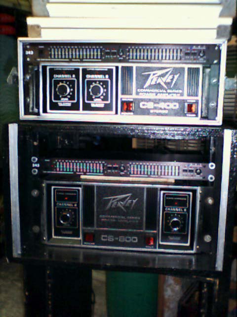
CS-800 & CS-400 Parts
CS-800 Power: SJ6343B, 7040-83180, MJ15024, ECG388. (NPN)Driver: SJ6387. (NPN)
CS-400 Power Transistor: SJ6357, 70484140. Driver: SJ6344. (NPN)
Drive Board: 6018 (NPN/ECB), 6019 (PNP/ECB)
6530-1 = 2N3642 / 6533-4 = 2N3638
7204 = 2N6557, MPSU10, ECG171 (NPN/EBC)
7205 = MPSU60, ECG296 (EBC)
690 = 2N4249, ECG159 (ECB) / 953 = SK3919, ECG822 (EBC)
761 = 2N5400 (EBC)
576/FET = 2N5461
Output Triac: SAC187 Bruce MAC223)/ Diac: SBS14
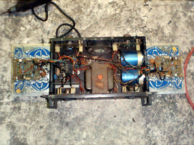
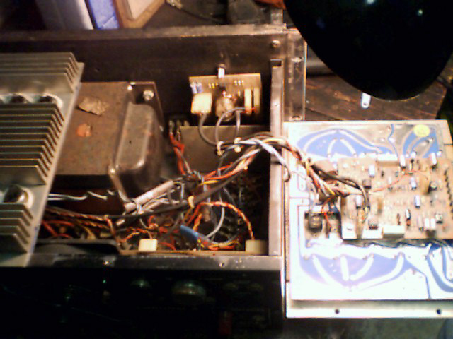
Remove the cover and both
output boards laying each board & assemblies upside down on each side of
the amp. Replace fuse and rig the power cable of the amp in series with a 150watt
light bulb for testing.
Upon power up the bulb will glow brightly and the fuse will not
blow.
Unplug each power cable on the output boards and attempt to see which side of the amp is causing the short. You would be turning on and off the amp each test and watching the bulb. When you find the bad side and unplug it the light will glow dim and the amp will power up and the other channel can be tested for signal.
Check all output transistors on the bad board replacing them as necessary. If you have a transistor tester then you can match transistors according to gains in order to balance and strengthen the output board. It is always desirable to replace them all but costly. While the transistors are removed also check the tolerance on the supportive resistors.
Replace all bad parts and check across the banana jacks to see if the output triac is shorted. Always compare readings with the working channel if you are not sure. This is found right at the speaker jack. A protection circuit to save your speaker should the amp malfunction. If it is shorted then replace it. To simply test fire the channel you are working on you can remove it.
Now plug the power cable back into the re-built board leaving drive board removed. Power amp up and light should glow dim. Now install the drive board and re-assemble the amp. Always make sure you blow out the amp with an air hose. Power up the re-assembled amp with the drive boards bolted in place and cover removed. If light glows dimly, then check for audio signal by hooking up a speaker and some input source. If you have problems with signal you can swap the drive boards around to determine if one of them also needs repair.
If the amp works, then unplug all the cables from it and plug the amp into direct power bypassing the bulb. Power amp up and see if one or the other output boards are developing heat. If so, refer to section on overheating. If you are ok, then set the cover back on top for proper airflow to cool the unit. Hook up a speaker to each side and listen for any AC hums. If you have a hum, bad solder joints on output transistors is most common or mismatch on your new parts. However, hums can be caused by many other problems all the way down to the power supply and is a different issue. A small hum is normal, but should not be noticeable when amp is used.
Now hook up an ohmmeter set
to 50 AC volts or more to the banana jacks. Hook up a dummy load speaker that
will absorb at least 500watts of power and stay at 8 ohms to the speaker port.
Inject a signal that will run the amp up to full power where when the knobs
are pushed in and the clip light blinks you should read CS-800 around 20 volts.
Switch this test signal back and forth between amp channels to make sure amp
is balanced and one side is not week. Pull out the knobs and input a stronger
signal momentarily to each channel and you should read around 45-50 volts when
amp is solid clip full tilt. Normally this is not a good way to run your amp
however momentarily as a test is needed to see if the channel is putting out
the correct power and pushing the knob back in verifies the DDT compression
is working correctly. DDT will clip a bit earlier than the raw amp with the
DDT disabled at the threshold point of clip. Pulling knobs bypasses the DDT
circuit and operates as raw power.
When the amp gets to hot it should do one of 2 things.
1. The fan should switch into high speed (internal sensor)
2. The amp shuts down completely. Power switch light goes off
and fan switch light comes on.
The amp has shut itself down to cool. If you put a fan on it,
it will help temporarily. The amp needs to be blown out with an air compressor.
Remove cover & both output boards to clean thoroughly
Replace power boards leaving cover off. Power the amp up with
nothing plugged in to it and feel each power board to see if it develops and
heat. If one gets hot quickly, unplug the amp. Re-heat the solder joints on
the output transistors and check to see if one of the output triacs are shorted
by using a continuity or ohm check on the banana jacks.
If you are still having troubles you will need to have a closer
look into the power board checking resistors for tolerance and solder joints
on output transistors. Make sure if you mess with output transistors that you
wipe them off and use fresh heat sink compound and a good insulator. Replace
any that are broken or cracked.
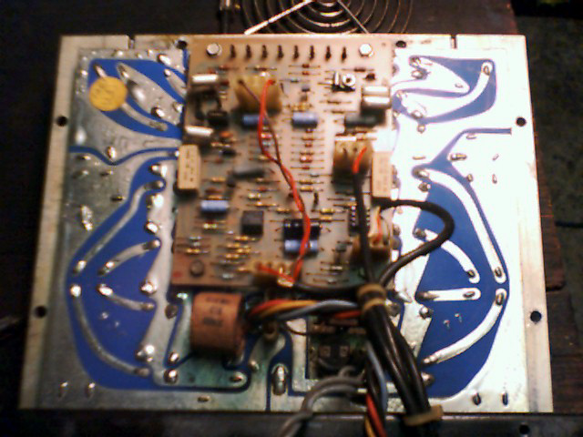
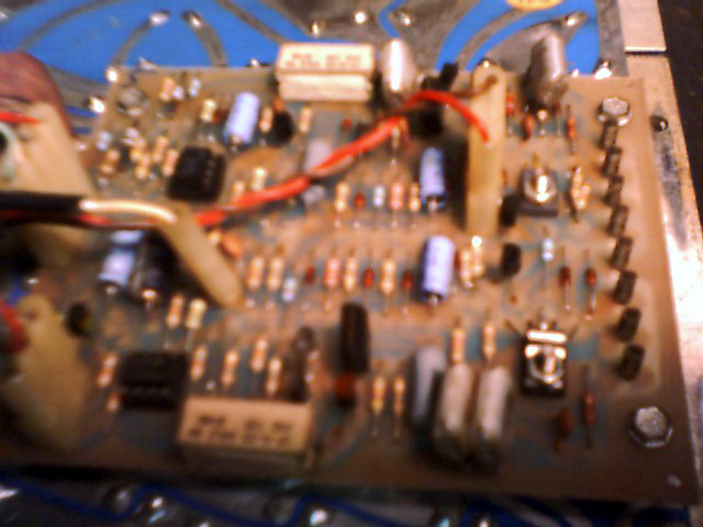
This is a drive board
problem. You can prove this by swapping them from channel to channel or using
a good side of the amp for a test bed. A common problem that drive boards have
is an open 47k resistor. Also, the FETs can be bad. To check the 47k
you will need to lift one leg and use an ohmmeter. Always compare resistors
to a new one when using analog meters. Week resistors will show a more open
circuit or a higher value. The rest of the transistors on this board can be
checked normally and gained out as well. Also check tolerances on the 2 big
block resistors on each side of the board. Toward one of these sides where there
is one large and one small transistor close together is where you will find
the 47k as well. As far as the FET is concerned, it's primary function is to
supress overload. If you have no signal and you want to check it, simply remove
it from the circuit.
When the clip light comes on constant and there is low volume output untill DDT compression is defeated by pulling knobs out, check the opp amp RC4558p
Circuit board where the volume knob is needs to be removed and
heat the volume pot pins and other key points for cold solder joints. Clean
up pins where jumpers hook in and tin the leads for a good connection. If you
run the device in test mode (series with a 100 watt light bulb to the power
plug of amp), you can move jumpers around while injecting a signal and probe
through with a signal tracer checking flow through circuit to find actual spot
of problem. In some cases this may be a drive board problem, reverse drive boards
and use the good channel for a test bed.
![]()